
Description
Every single piece of hardware that we ship out the door here were manufactured using our very own Reflow Oven Controller Shield. And we have sold countless number of them over the years and we are glad that it help many people to start reflowing their own SMD components in a reliable and repeatable manner. Along the way, we received many feedback from users and we took those feedback seriously and incorporate them in a new all-in-one reflow oven controller. Powered by the ATtiny1634R coupled with the latest thermocouple sensor interface IC MAX31856 from Maxim, we managed to remove the need of an Arduino board and reduce the overall cost. We also use as much SMD parts in this revision to keep the cost low (manual soldering and left over residue cleaning is time consuming) and leaving only the terminal block and the LCD connector on through hole version. We also managed to streamline all components to run on 3.3V to further simplify the design. All you need is an external Solid State Relay (SSR) (rated accordingly to your oven), K type thermocouple (we recommend those with fiber glass or steel jacket), and an oven of course! You can now select to run a lead-free profile or leaded profile from the selection switch. The example code running the reflow process utilized a PID control provided by the awesome PID library written by Brett Beauregard. Features:
- Powered by ATtiny1634R (thank you Spence Konde for the awesome work on the ATtiny core)
- We chose the “R” version for more accurate internal oscillator on the ATtiny1634R
- The current firmware only uses 10kB of the 16kB program memory flash and half of the 1kB RAM leaving lots of room for tinkering
- MAX31856 thermocouple interface
- Immersion gold finish allows easier soldering
- 8×2 LCD black character with yellow back light
- 2 push button connected to a single analog pin:
- 1 to start and stop the reflow process
- 1 to select the reflow profile (lead-free or leaded) and stored on the non-volatile EEPROM
- 1 red LED for status indication
- 1 terminal block for thermocouple type K
- 1 terminal block for driving SSR (through a NPN transistor) to control heating element/oven
- 1 buzzer with transistor for loud and annoying sound
- 1 reset button
- ISP pins breakout
- FTDI 6-pin breakout for firmware upload and serial interface
- Unit is powered through a microUSB connector or the FTDI 6-pin header
- Dimension – 40.00 mm x 51.00 mm
- RoHS compliant – Yes
This is a very dangerous project if not being handled carefully. Please take extra precaution and other safety measure when dealing with high voltage. Never ever have exposed high voltage wires lying around. It can be fatal. We would rather hear about how great your board looks like after using the tiny reflow controller rather than anything else. Take care.
Things You Need
| Item | Description |
| Oven | 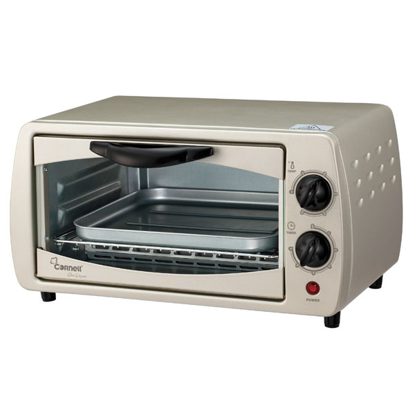 The oven selection is a very subjective process. We have tried a lot of oven in the past ranging from tiny 800 W to bigger ones with 1500 W output power. 2 important points: The oven selection is a very subjective process. We have tried a lot of oven in the past ranging from tiny 800 W to bigger ones with 1500 W output power. 2 important points:
|
| Type K Thermocouple | 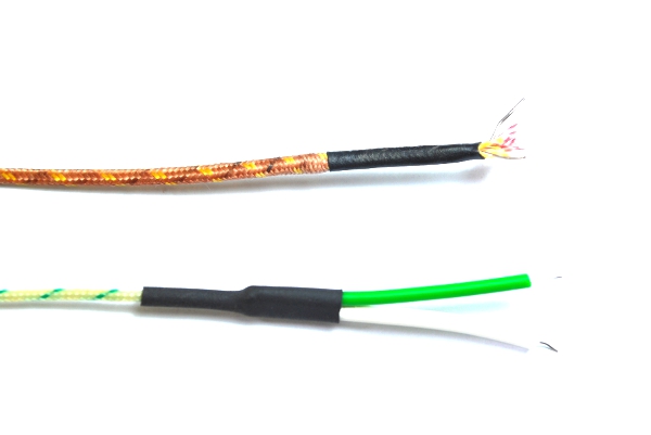 Get those with fiber glass or steel insulation jacket. Check the maximum temperature the wire can sense and we advise to choose those with higher than 500 °C. Don’t be stingy! Also take note of the maximum temperature the insulation jacket and make sure it can withstand the high reflow temperature. Recommended thermocouple includes offering from Omega. Don’t simply get some unknown thermocouple wire without any proper specifications. We are using the type K thermocouple shown below. Notice the difference of color on the insulation jacket which is based on US & Canada standard (yellow & red) and international standard (green & white). Yellow and green indicates the positive lead (Nickel – Chromium). Red and white indicates the negative lead (Nickel – Aluminium). Get those with fiber glass or steel insulation jacket. Check the maximum temperature the wire can sense and we advise to choose those with higher than 500 °C. Don’t be stingy! Also take note of the maximum temperature the insulation jacket and make sure it can withstand the high reflow temperature. Recommended thermocouple includes offering from Omega. Don’t simply get some unknown thermocouple wire without any proper specifications. We are using the type K thermocouple shown below. Notice the difference of color on the insulation jacket which is based on US & Canada standard (yellow & red) and international standard (green & white). Yellow and green indicates the positive lead (Nickel – Chromium). Red and white indicates the negative lead (Nickel – Aluminium). |
| Solid State Relay (SSR) | You’ll need an SSR with DC control voltage that can be driven directly from an Arduino pin. We are using a Crydom D2410 SSR that can drive a maximum load of 10 A with a control voltage range of 3-32 VDC. At 5 V, it requires only 5 mA to drive the control pin of the SSR. The maximum load current depends on your oven size. |
Controller Board
The Tiny Reflow Controller does not require any separate Arduino board to operate. The controller is shipped pre-loaded with the latest firmware which is made available on the GitHub repository.
Thermocouple Setup
It’s best to place the tip of the type-k thermocouple on one of the available through hole pads on your PCB. If there are no through hole available, you can also use a Kapton tape to fix the tip of the thermocouple onto the PCB. This will provide accurate temperature reading of the PCB and the components rather than the air temperature in the oven.
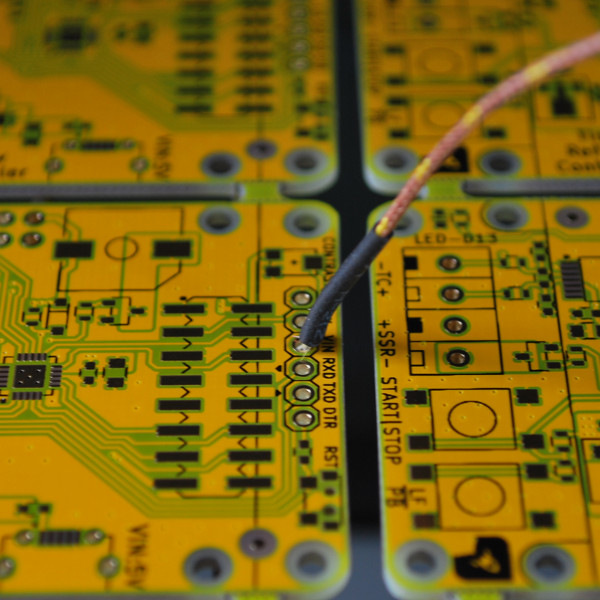
The thermocouple leads must be inserted into the terminal block with the correct polarity. To check whether your polarity is correct, rubbing the tip with your fingers should increase the temperature reading. If the temperature reading drops, you probably have inserted them in the wrong polarity. Swap the thermocouple leads connected to the terminal block to correct this.
Another important aspect to check is to make sure at the terminal block end, the two thermocouple leads are not touching or shorted together. You can check this by again rubbing your fingers on the tip of the thermocouple. If the temperature reading doesn’t increase or decrease and hover around the room temperature by a margin of few º C, then recheck the thermocouple leads to see whether they are shorted.
Solid State Relay (SSR) Setup
The controller has a 3.3V 5 mA output drive that can be used to drive DC-AC SSR. These type of SSR are commonly available with control voltage range of 3-32VDC. It usually requires minimal drive current like 5 mA or less to operate. The amount of output current and it’s AC voltage rating differs from model to model. Depending on your oven rating, you will need to select a suitable SSR with the corresponding output current capability.
There are many ways to wire up the SSR connection to your oven. We prefer the less invasive way without taking apart the oven. Here’s how our SSR and power plug setup looks like:

The grey color power junction box houses the SSR. Here’s how it looks like inside:
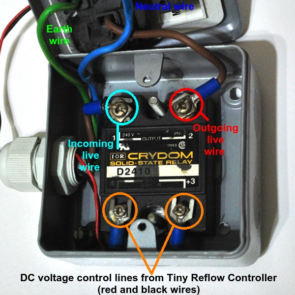
We strongly advise carrying out this step with extra care. Your life is at stake here.
Power Requirements
The controller board can be powered by using a FTDI (or compatible) USB-Serial adapter that has 5V supply on the VCC pin like our FT230XS board. However, please take note that the serial IO pins are operating at 3.3V. Using a FTDI board with the serial IO operating at 5V will damage the board. For example, our FT230XS board has an option of having a 3.3V or 2.85V serial IO voltage and at the same time the voltage present on the VCC pin can either be 2.85V, 3.3V or 5.0V (labelled as VCC SELECT in the picture below). If you choose to use a FTDI USB-serial adapter to power the board, you will need to solder a 1×6 2.54 mm male header onto the board.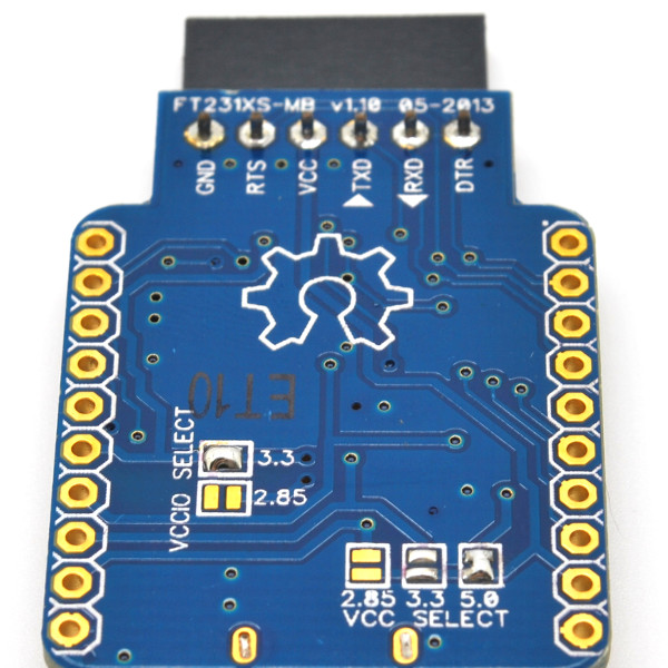
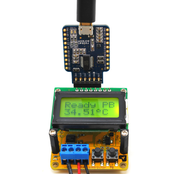
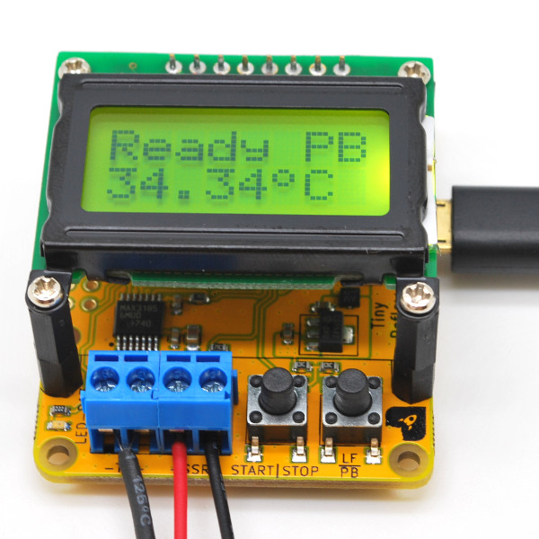
The board can also be powered the on-board USB micro connector. It’s best to use a less noisy USB power supply as thermocouple interface circuitry is very sensitive external noise. Even better if the USB cable comes with a ferrite bead or choke.
Oven
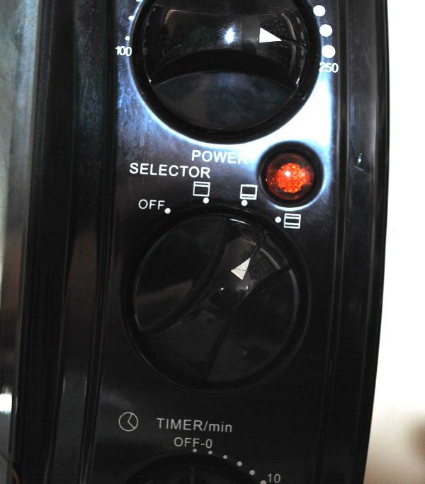
There’s not much setup for the oven other than turning the temperature knob to maximum (usually it is 250 º Celsius), heater element selection to all (if available) and timer to at least 10 minutes for a single reflow cycle.
Power Up
As mentioned in the previous section, the power to the board can be supplied either through the 6-pin FTDI header or the micro USB connector. Upon power up, you should the a splash screen of the product name, firmware revision and date.
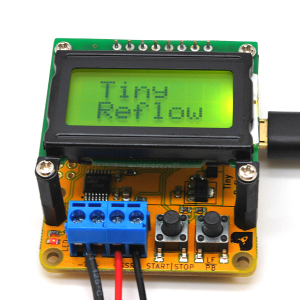
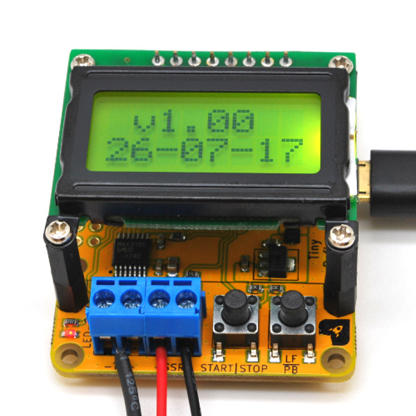
Reflow Profile Selection
Both lead free and leaded reflow profile is supported on the controller. The profile can be selected through the LF|PB switch only when the controller is in the ready mode. This is to avoid switching profile half way through the reflow process. A press of the button toggles the profile between the two. Once selected, the selected profile setting will be saved in the non-volatile EEPROM memory. Selected reflow profile will be shown on the top most right of the LCD indicated by LF (lead-free) and PB (leaded). Make sure you know what type of solder paste you are using.


It is also important to know that if you are selecting the lead-free profile, all your components and PCB specifications must be suitable for the higher temperature range in lead-free reflow process.
Let’s Reflow
Once you have place your components populated PCB into the oven with the thermocouple tip on the correct position on the PCB, you can press the START|STOP button to start the reflow process. Please note that, the process only starts if it is currently in ready mode and the temperature is below 50 º Celsius (to prevent components from experiencing thermal shock).
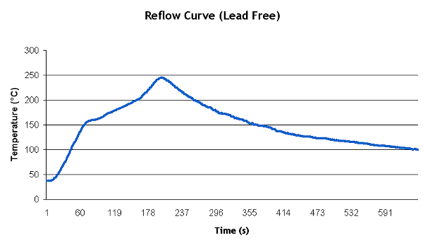
The first stage of the reflow process is the pre-heat stage. During this stage, the controller will ramp up to 150 Celsius faster than 1º Celsius per second and less than 3 º Celsius per second rate. Most oven (all oven that we have tried) will not be able to go faster than 3 º Celsius per second.
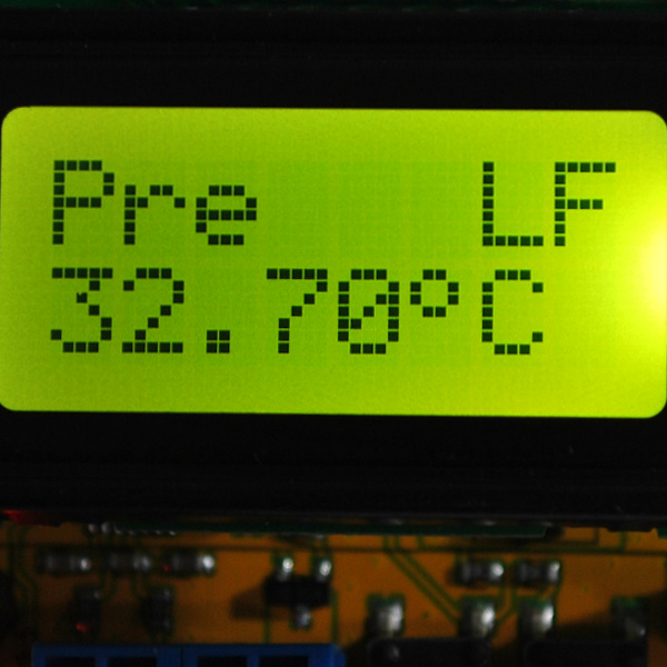
Once it reached the 150 º Celsius mark, the process will enter into the soak stage. As it’s name implies, in this stage the temperature increment will be slowed down until it reaches the 180 º Celsius for leaded profile (or 200 º Celsius for lead-free) in which it will then enter the reflow stage.
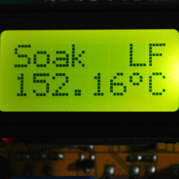
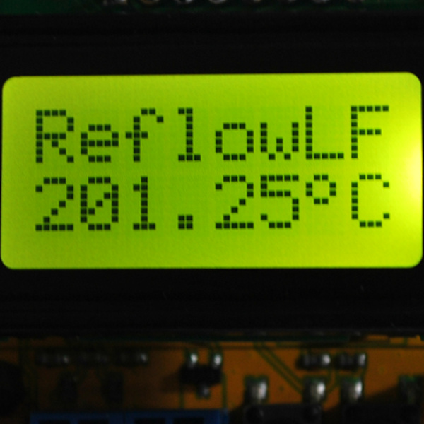
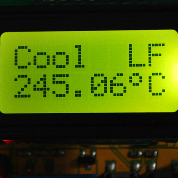
During the reflow stage, the controller will ramp up in the similar manner as the pre-heat stage, until it reaches the peak reflow temperature (218 º Celsius for leaded and 245 º Celsius for lead-free) and the cooling down stage starts. During this stage, the controller will shut off the SSR (and hence the power to the oven) completely. You are advise to open the oven door slightly to help the cooling process. Any cooling down rate faster than 6 º Celsius is not recommended and will cause thermal shock and stress on the components.
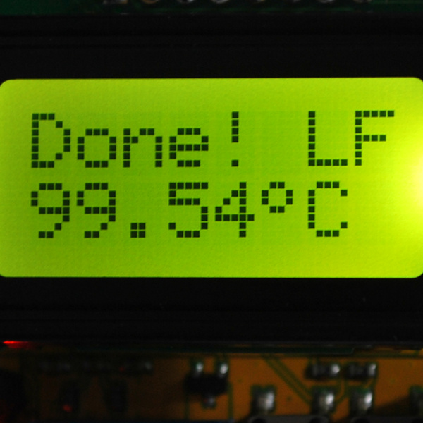
Once the temperature of the board cools down to 100 º Celsius, the reflow process is completed and the buzzer sound can be heard. Let the board temperature cools down to room temperature before removing them from the oven because it will be very hot to handle them.
Examining Reflow Profile
It is advisable to do an initial run using a blank PCB and connecting a FTDI (or compatible) USB-serial adapter to a serial terminal to analyze the temperature curve. In 9 out of 10 oven setup, the temperature profile achieved would most probably work without any modification to the firmware. Use any serial terminal program at 115200 bps 8N1 configuration to collect the temperature information across time.
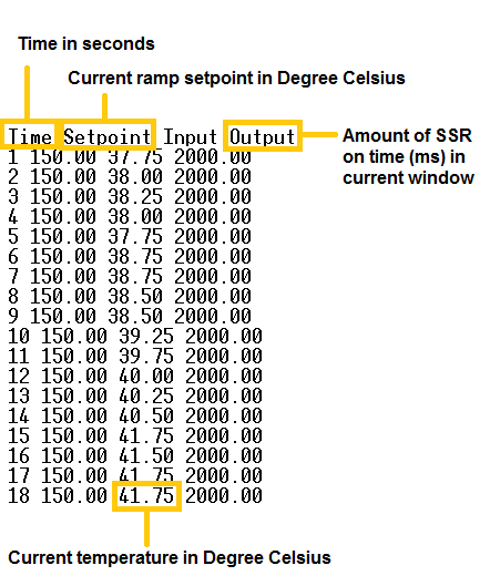
You could then use any chart plotting program like Microsoft Office’s Excel (or if you are on open source software like us, you can use LibreOffice Calc) to plot the temperature curve against time. A typical lead-free temperature curve plot would look like this (oven door is open slightly once the process reach the reflow peak temperature):
How Does a Perfectly Reflowed Board Looks Like?
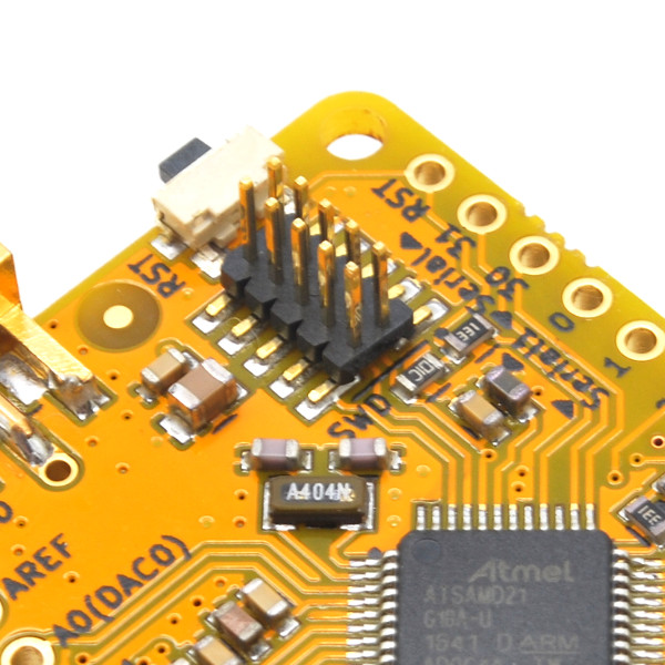
All the boards made here are manufactured by the Tiny Reflow Controller itself. Just take a look at the SMD solder joints of the board. It should as great as that!
The Tiny Reflow Controller is capable of detecting certain errors. This is usually indicated by the “TC Error” message on the LCD. These errors are detected by the on-board MAX31856 thermocouple interface chip.
“TC Error” usually occurs due to several reasons:
- The tip of thermocouple is touching the ground of the system. For example, the metal grill of the oven which touches the oven chassis is earthed by default. Just make sure the tip is not touching them as it will short the thermocouple input signal to the ground level.
- The thermocouple wire used is of those metal body type. Again, if it touches any source of ground like the above, the error will be triggered.
- No thermocouple is present or the thermocouple wire lead is loose/not properly connected to the terminal block. As the thermocouple wire is small in comparison to the terminal block clamp, this is usually the case. Tighten the terminal block screws properly and try pulling them out, the thermocouple lead should not come out.
- Very noisy power supply is used. Although we have included a ferrite bead (L1) close to the USB micro 5V source and also damping resistors (R2 and R3) on the thermocouple inputs to reduce any possible external noise coupled into the system, thermocouple sensors are very sensitive to noise. On previous Arduino shield version of this controller, this is usually the case because some people uses clone Arduino board that has noisy power supply section. But, as the Tiny Reflow Controller is an all-in-one design, this is less likely to happen but as a precaution, just make sure you are using a decent clean USB power supply.
The controller will halt any reflow process and will not start if the error is present.
If you think you want to make some changes to the controller, the board provides a standard FTDI (or compatible) USB-serial 6-pin breakout. This can be used to upload code through the Arduino IDE. The on-board ATtiny1634R microcontroller uses the ATtinyCore written by Spence Konde. Please make sure you have install the ATtinyCore through the Arduino IDE Boards Manager.
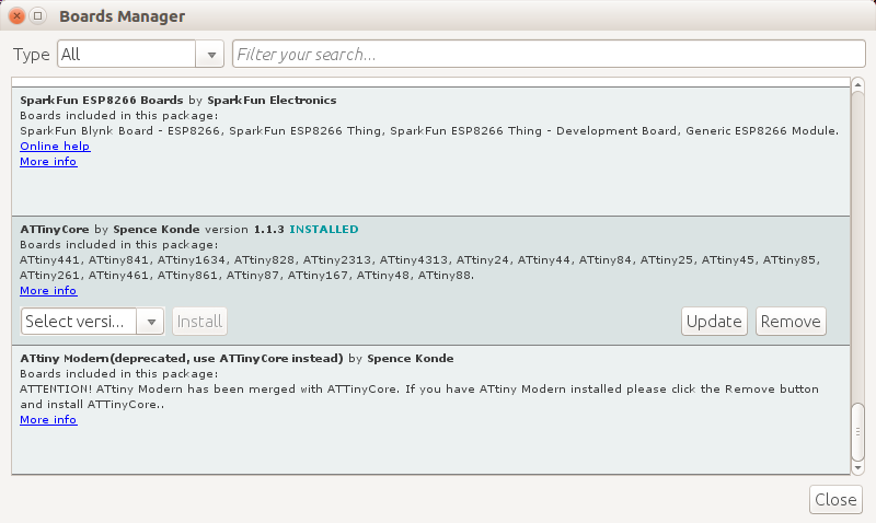
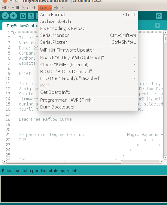
Once the ATtinyCore board package has been installed, you should select ATtiny1634 (Optiboot) with the 8 MHz internal clock:
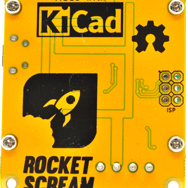
If you are more adventurous and would love to ditch the Arduino IDE altogether or would like to load the firmware directly without the FTDI header, the ICSP pins of the ATtiny1634R is made available at the back of the controller board.
If you made some changes to the firmware or made some hacking to the hardware, we would love to hear it from you!
The Tiny Reflow Controller is an open source product. All the design files and firmware can be downloaded from our GitHub repository.
Oven builds by customers are available on the forum here.


