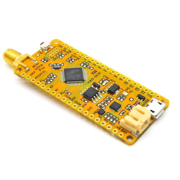
This is our low power rendition of the Arduino Zero based on the 32-bit ARM Cortex M0+ ATSAMD21G18A that provides plenty of processing power and peripherals at a reasonable cost. Mini Ultra Pro is the result of years of designing boards used for low power wireless sensor network applications in remote area. Many design aspects were based on improving the shortcomings of previous deployed projects like not having enough program flash memory, slow processing speed, unsuitable battery charger, limited range radio, unreliable data logging memory type and many more. We spent many hours and numerous board revision before actually releasing the final version. Here’s a short summary on the Mini Ultra Pro specifications:
- Compatible with Arduino IDE using “Arduino/Genuino Zero (Native USB Port)” as the board option
- Microcontroller – ATSAMD21G18A-AU
- Clock – 48 MHz
- Operating voltage – 3.3 V
- Low quiescent current (1.6 μA) on-board 3.3 V 250 mA low dropout regulator
- Ultra low power – Minimum 20.0 μA in sleep mode (known as standby mode on ATSAMD21G18A-AU) with a 4.2 V Li-Ion/Li-Pol battery as power source
- External DC source range – 5 – 10.5 V (over voltage protection up to 28 V)
- Battery charging management:
- Power path management for proper charging process and load balancing
- 400 mA battery charging current
- 2 indicator LED for power good and charging process indication
- Suitable for battery operation (3.6 V Lithium-Ion/Polymer)
- Radio transceiver module options:
- RFM95W 20 dBm long range LoRa radio module (915MHz or 868MHz):
- Tested range with our 5 dBi antenna in semi urban area of 8 km (SF = 12, BW = 125 kHz, power = 20 dBm, frequency = 915MHz)
- RFM69HCW 20 dBm FSK radio module (915MHz or 868MHz):
- Tested range with our 5 dBi antenna in semi urban area of 1 km
- Uses the multi platform RadioHead Packet Radio library for embedded microprocessors
- RFM95W 20 dBm long range LoRa radio module (915MHz or 868MHz):
- On-board 2 MB (16 Mbit) serial flash for data logging
- On-chip RTC with calendar support (using the RTCZero library)
- Indicator LED connected to digital pin 13 through a MOSFET
- 500 mA fuse for USB port over current protection
- USB micro connector with 4 through hole pegs for reliability
- JST PH 2.0 mm battery connector for Li-Ion/Li-Pol batteries
- Side reset tact switch for easy access
- Native USB serial for code upload
- 10-pin 1.27 mm pitch for ARM Cortex SWD
- 900 mil in between 2 breakout headers – suitable for breadboard usage
- Dimension – 25.4 mm x 55.88 mm (1.0″ x 2.2″) (without the SMA connector)
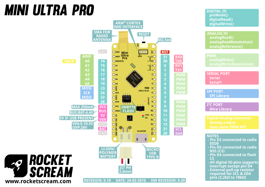
Power Pins
The power pins available on the Mini Ultra Pro are as follows:
- GND – The common GND for the board.
- BAT – Li-Ion or Li-Polymer battery input positive supply. Battery power is supplied to the board through the JST 2.0 mm connector.
- VIN – External voltage input positive supply. An input voltage range of 5-10.5 V is allowed (recommended 5.5V) and over-voltage protection up 28V is provided.
- 5V – USB 5 V supply if the micro USB is connected.
- VBUS – The positive voltage output from the on-board power management/charger IC. VBUS is the output derived from the VIN, BAT or both at the same time. Voltage range is from BAT up to 4.4 V. All subsequent voltage rails (if required) should be derived from this VBUS supply.
- 3V3 – Output from the on-board 3.3 V LDO regulator. A maximum of 250 mA of current can be supplied by the regulator. All the on-board circuit components are powered by this 3.3 V supply including the microcontroller, serial flash and radio module.
Digital IO
All digital IO pins are 3.3 V tolerant and you are not supposed to apply any voltage higher than 3.3 V on them. Each pins can only draw/sink maximum of 7 mA of current. All pins can have external interrupt except pin D4.
Analog IO
There are 6 analog input (A0 to A5) pins that have up to 12-bit ADC resolution (10-bit is the default configuration) and can measure voltage input from 0 to 3.3 V. Pin A0 is also an analog output pin (Digital to Analog Converter) where you can output voltages from 0 to 3.3 V in 10-bit resolution steps. By applying an external reference voltage (< 3.3 V) on AREF pin and reconfigured using the analogReference() API in the firmware, the voltage input range on the analog input pin can be reduced to increase the voltage resolution. [av_notification title='Warning' color='red' border='' custom_bg='#444444' custom_font='#ffffff' size='large' icon_select='yes' icon='ue83e' font='entypo-fontello' av_uid='av-d5h27n'] Do not apply voltages higher than 3.3 V on the analog input pins. It will damage the board. [/av_notification]
PWM Output
Pin D2, D3, D4, D5, D6, D8, D9, D10, D11, D12, and D13 can provide PWM output with 8-bit resolution (can be configured as 12-bit).
USB
The USB pins are connected to the micro USB type B connector and sketch can be uploaded through this USB serial interface. It can also be used as a general debug port for your application.
Serial Port
There are 2 serial port available on the board:
- Serial – RX0 on pin D31 and TX0 on pin D30. On Arduino, it can be access using Serial.begin(), Serial.println(), etc.
- Serial1 – RX1 on pin D0 and TX1 on pin D1. On Arduino, it can be access using Serial1.begin(), Serial1.println(), etc.
SPI Port
The SPI port are provided by the MISO, MOSI, and SCK (on pin D22, D23, and D24 respectively). The SPI port is connected to the on-board serial flash and radio module. The serial flash uses pin D4 and the radio module uses pin D5 as the chip select (CS) pin respectively. The radio module also uses pin D2 as an external interrupt pin. These pins (D2, D4, and D5) must not be used by user application circuitry.
I2C Port
The I2C port are provided by the SDA and SCL (on pin D20, and D21 respectively). External pull-up resistor (values from 2.2 kΩ to 10 kΩ) is required when interfacing with other I2C bus devices.
Reset
Reset signal for the microcontroller which is also connected to the tact-switch located at the top of the board.
LED
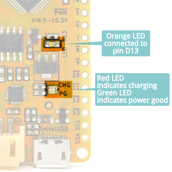
They are 3 LED on the Mini Ultra Pro. An orange color LED is connected to pin D13 through an N-channel MOSFET. Another 2 LED (a common anode dual LED in a single package) provides the status of the power management IC.
- Green LED – Light up if the power supply input is within the valid range (from the VIN, USB or both) of 5 to 10.5 V. The LED will also light off if an over voltage supply range is detected (> 10.5 V at the VIN pin).
- Red LED – Light up if the charging process is on-going. Light off if no charging is taking place or charging process has been completed.
ARM® Cortex SWD Interface
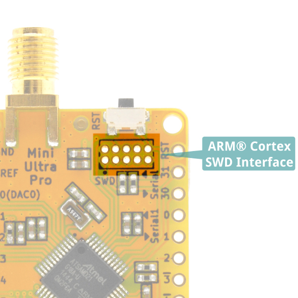
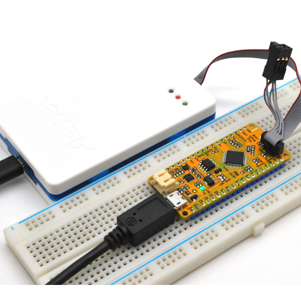
A standard ARM® Cortex SWD Interface is provided through a 1.27 mm pitch 5×2 pin connector. If you plan to program the board without the Arduino environment (for example through Atmel Studio), a programmer like the Atmel ICE can be used.
Serial Flash
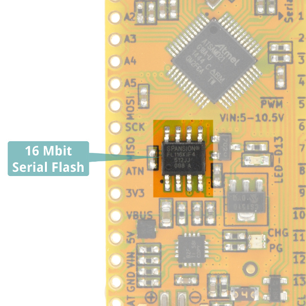
A 16 Mbit (2MByte) Spansion S25FL116K0XM serial flash is available on the Mini Ultra Pro for data logging such as sensor readings and configuration information. The serial flash communicates with the ATSAMD21G18A-AU microcontroller through the SPI interface with pin D4 as the chip select pin. Do not use the pin D4 for user application circuitry unless you remove the serial flash from the board.
Radio Module & SMA Connector
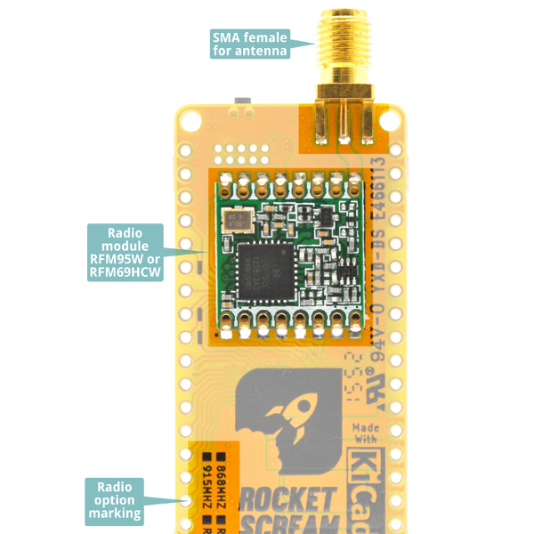
The Mini Ultra Pro comes with the option of a radio module. 2 radio module type are available:
- RFM95W – Primarily a 20 dBm LoRa enabled radio module (although capable of running in FSK mode too) with ultra long range capability (up to 8 km using our 5 dBi dipole antenna in semi urban area). Both 868 MHz and 915 MHz options are available. Suitable for infrequent slow data transmission and long transmission range.
- RFM69HCW – A 20 dBm FSK radio module. Both 868 MHz and 915 MHz options are available. Suitable for more frequent faster data transmission (compare to RFM95W), shorter transmission range (few hundred meters) and cost sensitive solutions.
The Mini Ultra Pro comes without any header or receptacle mounted. This gives you the freedom of using several types of connector depending on your needs.
Male Header
The 2.54 mm pitch male header is the most common connector that can be used on the Mini Ultra Pro. Use this type of connector especially when you are still prototyping on a breadboard. All Mini Ultra Pro comes with a free 2.54 mm pitch 1×40 pin male header.
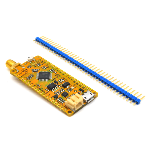
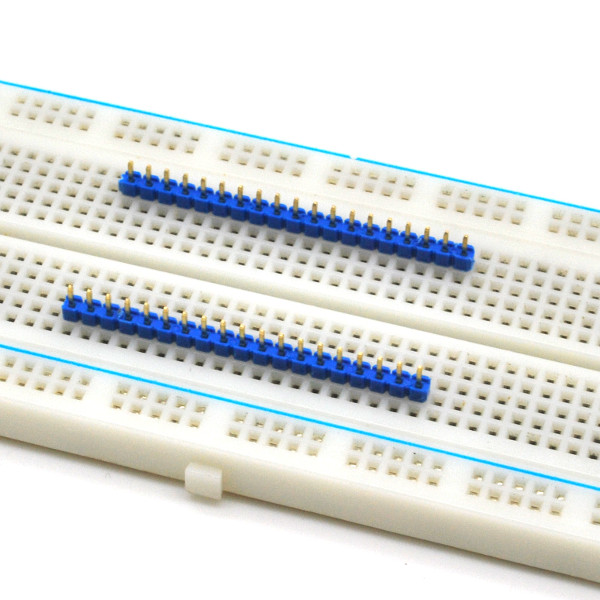
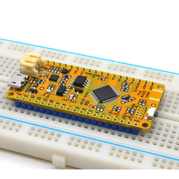
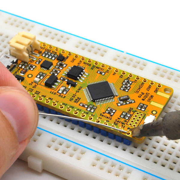
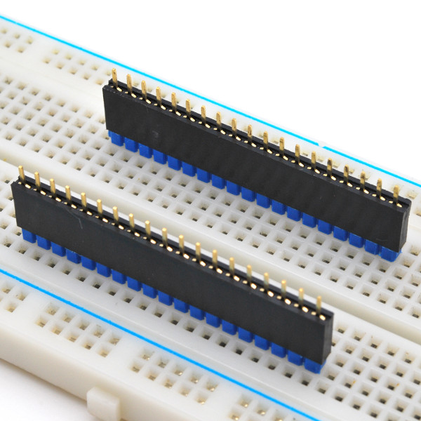
To solder the male header, you would first need to cut the 1×40 pin header into 2 pieces of 1×19 pin header. We would usually place the male headers on a breadboard align to the spacing in between the 2 rows of the breakout pins on the Mini Ultra Pro. Please make sure the shorter side of pin is facing upward.
Receptacle Header
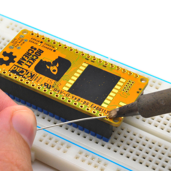
If you plan to stack an add-on (or shield) on top of the Mini Ultra Pro, a 2.54 mm pitch receptacle header can be used. We carry them in our store. To solder the receptacle header onto the Mini Ultra Pro board, we would usually use a same pin count male header inserted into the breadboard with the longer section of the pins facing upward.
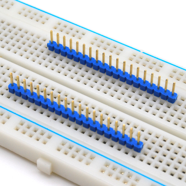
We would insert the receptacle header onto the male header before soldering them onto the Mini Ultra Pro board.
Stacking Header
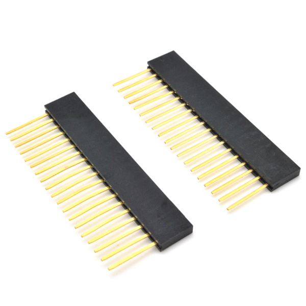
If you are used to the stacking header system used in Arduino boards and shields, we do carry them in our store. By using these long pins stacking header, you can stack at least 2 or more add-on board (shield) onto the the Mini Ultra Pro.
Soldering the stacking header onto the Mini Ultra Pro board is similar to the regular receptacle header.
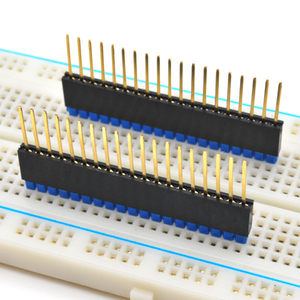

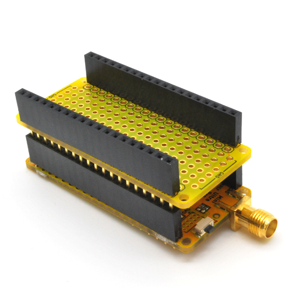
An example of Mini Ultra Pro using a receptacle header paired with a Proto Shield.
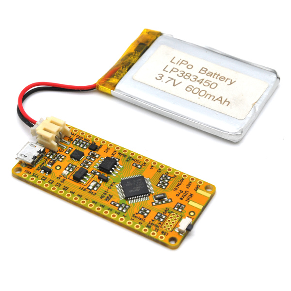
The Mini Ultra Pro is very versatile when it comes to power requirement. The power circuitry has been designed with low power consumption as the main criteria. The easiest way to power the Mini Ultra Pro is using a Li-Ion or Li-Polymer battery. We recommend using a battery with a capacity of 400 mAh or more as the charging current is set to 400 mA. It is recommended to charge Li-Ion and Li-Polymer batteries at the rate less than the capacity to improve the lifespan. A standard JST PH 2.0 mm connector is used. Unfortunately, we are unable to sell Li-Ion or Li-Polymer batteries due to their restriction on air shipment. Fortunately, they are widely available from other companies like from Sparkfun and Adafruit. In sleep mode, the Mini Ultra Pro only consume 20 µA with both the on-board serial flash and radio module put into sleep mode too!
You can also use a standard USB cable (with micro USB type B termination) to power the board. The USB supply will power the board and also charge the battery.
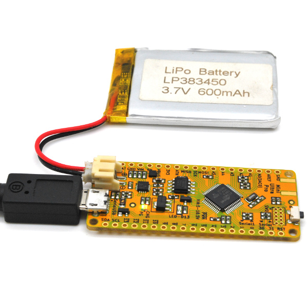
The power good, PG indicator (green LED) will light up when the USB cable is connected. The charging, CHG indicator (red LED) will light up if the charging process is taking place and a battery is present. Upon the completion of the charging process, the charging, CHG indicator (red LED) will light off.
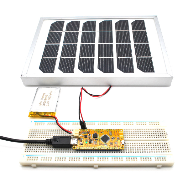
The Mini Ultra Pro board can also accept an external DC supply ranging from 5 V to 10.5 V. Over voltage protection up to 28 V is also provided at this VIN input pin. The power management IC on the board behaves close to that of a Maximum Power Point Tracking (MPPT) solar charge controller. If the input voltage on the VIN drops below a threshold, it will reduce the battery charging current to prevent the input voltage from further dropping beyond the usable level. This will prevent unnecessary multiple charging cycles that will eventually reduce your battery lifespan.
We recommend using a solar panel rated with 6 V open-circuit voltage (VOC) and with power rated higher than required charging current.
And of course if you are in a lab, you can also provide the board with the required DC voltage on the VIN pin.
Using the Mini Ultra Pro board with the Arduino IDE is pretty straight forward. On the latest Arduino IDE (v1.6.7), please install the Arduino SAMD boards extension under the “Tools >> Board >> Board Manager” menu. WARNING: Do not use Arduino SAMD v1.6.5 board package at the moment due to a critical bug.
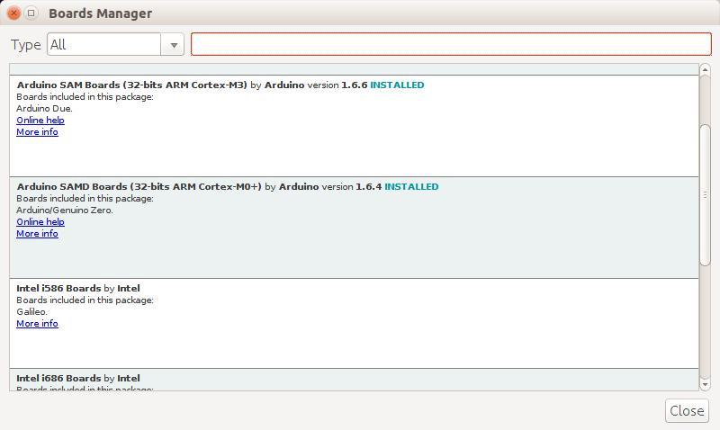
Once the extension is installed, you should be able to select the board as “Arduino/Genuino Zero (Native USB Port)” under the “Tools >> Board” menu.
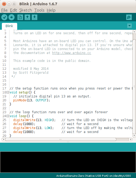
Now we are ready to upload our very first program on the Mini Ultra Pro. Attached the Mini Ultra Pro using an USB cable and select the correct corresponding USB COM port. Load the example “Blink” under the “File >> Examples >> Basic >> Blink” menu. The Mini Ultra Pro has an on-board LED (orange) connected to pin D13 that you would usually find on any regular Arduino board. Press the upload button and that shall load the program on the Mini Ultra Pro. You should be able to see the on-board orange LED blinking at a 1 Hz rate.
More tutorials on using the other peripherals on the Mini Ultra Pro is covered in separate guides.
Further readings on how to use a specific function on the Mini Ultra Pro are as follows:
- Using Mini Ultra Pro with The Things Network (TTN)
- Using Digital Analog Converter (DAC) on Mini Ultra Pro
- Using Real Time Clock (RTC) with Mini Ultra Pro
- Using RTC in Low Power Mode on Mini Ultra Pro
- Data logging with Mini Ultra Pro Coming Soon
- Using RFM69HCW FSK radio module with Mini Ultra Pro Coming Soon
- Rapid prototyping with Mini Ultra Pro Coming Soon
The Mini Ultra Pro is an open source hardware project:


