Introduction
TraLog is a combination of GSM-GPRS, GPS and micro SD in 1 shield. We added every possible feature that we could think of when making this shield. TraLog gives you the capability of GSM-GPRS connectivity, GPS tracking, and data logging capability all in 1 shield without having a 10 storey high shield stacks! We also came out with a simple Arduino compatible library for the WISMO228 GSM-GPRS module that allows you get started straight away without have to worry about messing with AT command (forgetting about the carriage return is a nightmare, ei?). For the MAX-6Q GPS module, you’ll need to use the TinyGPS library for NMEA 0183 sequence decoding and for the micro SD, you’ll need the built-in Arduino SD library. You can choose to run the shield off the VIN pin on the Arduino board or through a Li-Ion/Li-Pol cell. For you makers that is more adventurous, the MAX-6Q GPS module is a powerful and a very configurable GPS module. The WISMO228 GSM-GPRS module comes preloaded with the latest firmware (version L23) and necessary pins for future firmware upgrading (RX, TX, RTS, CTS) is broken out if newer firmware version are released. Now go and TraLog something!
Specifications
- Sierra Wireless WISMO228 GSM-GPRS module:
- Quad band (850, 900, 1800 and 1900MHz frequency bands)
- Low power consumption:
- 50uA in off mode
- 1.22mA in idle mode
- Embedded TCP/IP stack
- On-board RTC (2.5uA operating current)
- uBlox MAX-6Q GPS module:
- uBlox 6th generation chipset
- Up to 5Hz update rate
- 50 channels
- Tracking sensitivity -161dBm
- 1s hot start
- Micro SD & SIM card combo slot
- Step down switching regulator:
- 3.6V 3A
- Up to maximum 17V input voltage
- Minimal heat dissipation and low quiescent current (17uA)
- Able to operate directly with Li-Ion battery
- Li-Ion battery charger:
- Up to 1A charging current (default configuration: 100 mA)
- Charging status LED
- Up to maximum 16.5V input voltage
- Coin cell CR1220 battery backup for MAX-6Q GPS hot start
- Coin cell CR1220 battery backup for WISMO228 RTC
- Flexible UART lines selection for WISMO228 through simple jumper:
- Interface directly with PC (bypass ATMega chip from Arduino board) – useful when you want to try out the AT command directly
- Hardware UART on D0 & D1
- Software UART on D5 & D6.
- Supports Arduino Mega2560/1280:
- GSM-GPRS and GPS support via extension board:
- WISMO228 GSM-GPRS module – Select between UART1 or UART2
- MAX-6Q GPS module – Select between UART2 or UART3
- microSD connection through the ISP 6-pin connector (SPI pins)
- GSM-GPRS and GPS support via extension board:
- On and off control of WISMO228:
- Software control through pin A2 or
- SPNO tact switch
- On and off control of MAX-6Q:
- Software control through pin D9 or
- Permanently on
- RI (ring indicator) line on WISMO228 (selectable through jumper to pin D2) to provide new SMS indication and incoming call (you don’t have to worry about polling for new SMS or having a big buffer when multiple new SMS is in storage
- Time Pulse line on MAX-6Q (selectable through jumper to pin D3) to provide accurate 1s timing which is useful for situation where time based task execution is required
- GSM activity indication LED – You know when your GSM-GPRS is alive & kicking
- GPS status indication LED – GPS fix indication
- Voltage translation between Arduino board and shield
- Works with both 5V and 3.3V Arduino boards:
- Utilize the IOREF pin available on Arduino board version R3 and above to detect operating voltage
- Older revision of Arduino board is also supported through solder jumper
- Works with both 5V and 3.3V Arduino boards:
- ESD and transient protection on SIM card
- Edge SMA connector for both GSM-GPRS module and GPS module
- 2dBi GSM antenna (included)
- Active patch GPS antenna with 3m cable (included)
- Arduino reset tact switch
Things You Need
| Item | Description |
| Arduino Main Board | 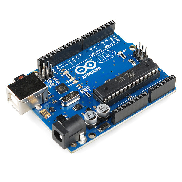
You can use any of the following board:
|
| TraLog Shield | 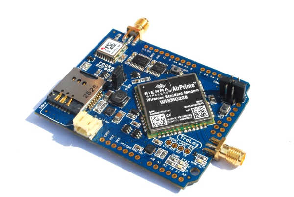 Preferably v2 of the shield. v1 does not support Arduino Leonardo and Arduino Mega2560. Preferably v2 of the shield. v1 does not support Arduino Leonardo and Arduino Mega2560. |
| SIM Card | A SIM card that is unlocked. |
| A µSD card | Formatted as FAT16/FAT32. |
| An AC-DC power adapter | Please ensure the current rating is adequate (recommended 2A) as GSM transmission burst consumes quite a bit of current. Voltage rating should be 7-17 VDC. Minimum 7V is required for the regulator on the Arduino board to operate. |
| Lithium Ion Battery | Get a decent size of Li-Ion of more than 1000 mAH. |
| GSM Antenna | 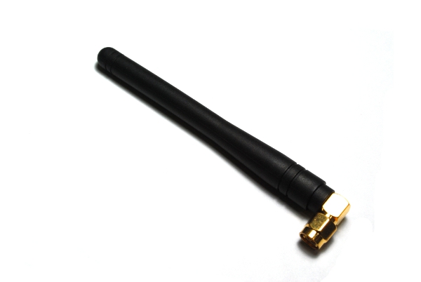
Included with the TraLog Shield |
| GPS Active Antenna | 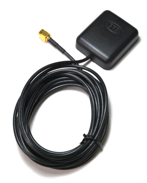
Included with the TraLog Shield |
Getting Started
General
In order to stack the TraLog shield to your Arduino board, we recommend using a standard 2.54mm (0.1″) male headers as shown below. Using male headers provides adequate room between your Arduino board and the TraLog shield. Don’t worry about the large USB connector (on an Uno and Mega2560) touching the TraLog shield. The PCB layout is designed in such a way that the section of the PCB that touches the USB connector are electrically connected to GND only (no short circuit will take place as the USB connector is electrically connected to GND too).
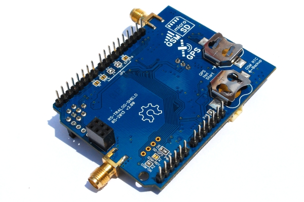
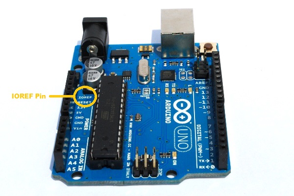
The TraLog shield supports both 5V and 3.3V Arduino boards. The on-board bidirectional voltage translator takes care the difference of voltages between the TraLog shield and the Arduino board. Since the introduction of the Arduino R3 pin layout, a pin called IOREF is used to allow any shield to detect the operating voltage on the Arduino board. For example, the Arduino Uno R3 and Arduino Mega2560 R3 below spots the extra IOREF pin.

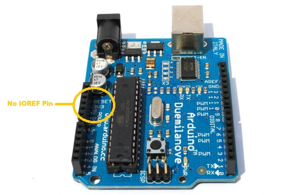
However, if you are using an Arduino board prior to the R3 pin layout like Arduino Uno R2 (and below), Mega2560 R2 (and below) or an Arduino Duemilanove (as shown below), a solder configuration jumper is provided to compensate the absence of this IOREF pin.
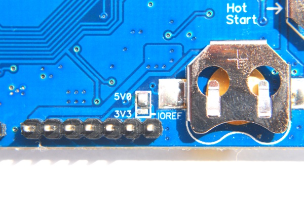
If you are using an Arduino board with the IOREF pin, you must leave the solder jumper open on both options. For Arduino board without the IOREF pin, short the jumper with a blob of solder to either 5V (if your board is a 5V board) or 3.3V (if your board is a 3.3V board) as shown below. TraLog shield v1 does not have this configuration jumper and assumes the VCC pin on an Arduino board is the operating voltage.
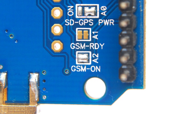
On v2 of the TraLog shield, the power supply to the μSD card and GPS module can be controlled by the Arduino board or permanently on. Even when the μSD is in idle mode, it consumes at least few hundreds of μA (varies from model to model and manufacturer to manufacturer). If your application requires low power operation, you need to short the jumper to the A0 position shown in the image below. You can now control the power supply to your μSD card and GPS module by toggling the A0 pin (logic HIGH to turn on, and logic LOW to turn off). But, if you decide to allow the SD card and GPS module to run all the time, you need to short the jumper to the ON position.
Only 1 solder jumper position can be used at a time.
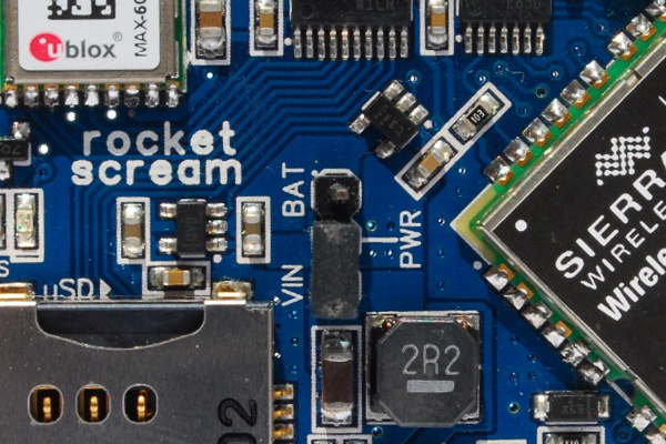
Powering the TraLog shield can be either from the external DC through the VIN pin or a Li-Ion battery. Short the power supply source jumper to the VIN position to use the external DC source. An external AC-DC adapter rated at least 1.5A is recommended in order for the GSM module to operate properly.
Maximum 17V is allowed on v2 and 30V on v1 (but Arduino main board can only take up to 20V maximum).
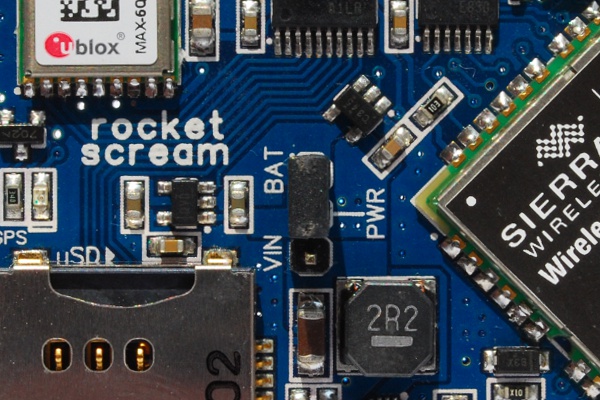
If you wanted the run the shield off the Li-Ion battery, short the power supply source jumper to the BAT position.
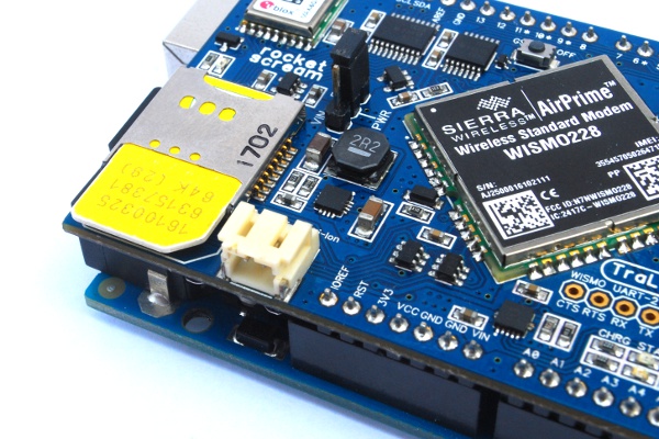
When a Li-Ion battery is connected to the shield via the JST 2.0mm standard battery connector, it will be charged provided that external DC source is available on VIN pin. The on-board Li-Ion battery charger charges the battery at 100 mA current. This current rating can be changed easily by replacing a current regulating resistor on the board to allow charging current up to 1000mA.
SIM Card
An unlocked mini sized SIM card is required for the TraLog to operate. We have decided not to provide API that enables the use of SIM card that requires pin number submission before use on our WISMO228 library. This is to avoid bricking your SIM card as only your service provider can unlock them.
µSD Card
The µSD card shares a common connector with the SIM card. The card should be formatted in FAT16 or FAT32 file system. The card can be inserted into the connector with the exposed card terminal facing upward.
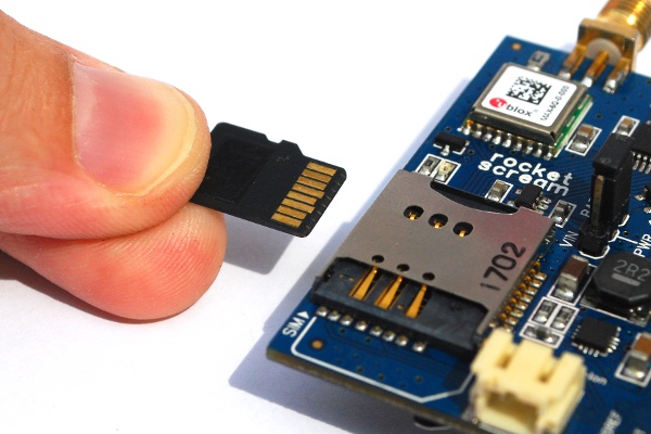
You should be able to hear a click sound once it is inserted correctly.

To remove the µSD card, you’ll need to push the card and it will slightly pop out from the connector.
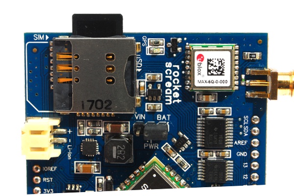
Pin assignment:
| Pin | v1 | v2 |
| MOSI | D11 | MOSI on ISP |
| MISO | D12 | MISO on ISP |
| CLK | D13 | CLK on ISP |
| SS | D4 | D4 |
Arduino Uno and Duemilanove SPI pins are available on pin D11-D13 on top of the ISP header connector, but this is not true for other boards such as Arduino Leonardo and Arduino Mega2560. On v1 of the TraLog shield, the SPI pins used for the µSD card interface is connected to pin D11-D13 on the female header. Therefore, the µSD card interface on v1 will not work with Arduino Leonardo and Mega2560 board as the SPI pins are solely located on the ISP header. If you are having a v1 shield and wanted the shield to work with Arduino Leonardo and Mega2560, you’ll need to make the following connections:
- D11 to MOSI (physical pin 3) on ISP header
- D12 to MISO (physical pin 2)on ISP header
- D13 to CLK (physical pin 4) on ISP header
v2 supports µSD interface for all boards out of the box as the SPI pins are connected to the ISP header.
Although pin D10 is not being used in the shield, please ensure D10 is configure as output to allow the SPI interface to work accordingly.
GPS Module
Depending on which version of the TraLog shield you have, you will either have the following GPS module on your board:
- EB3531 – SIRF-III chipset powered GPS module (v1)
- MAX-6Q – uBlox 6th generation powered GPS module (v2)
The GPS module is connected to the Arduino board through software serial implementation as there is no physical UART available on the assigned pins. We will need to use the SoftwareSerial library which is bundled in the Arduino IDE 1.0 and above.
The GPS module can be configured to operate at low power mode using the Arduino D9 pin.
On v1 of the shield, pin D9 is is used to control the ON-OFF pin on the EB-3531 GPS module which can be selected through jumper J19. But, if you decided to let the GPS module to run all full mode, you can short jumper J12 to ground (default configuration). Refer to the jumper configuration table at the back of the TraLog Shield board.
On v2 of the shield, pin D9 is is used to control the EXTINT0 pin on the MAX-6Q GPS module which can be selected through jumper J10. The EXTINT0 controls the tracking behavior of the MAX-6Q GPS module at low power mode to save power consumption while still providing tracking capability. Please refer to the MAX-6Q datasheet for further information.
Both GPS module provide a very accurate Pulse Per Second (PPS) signal output. This signal can be fed to the Arduino board pin D3 through jumper J16 on v1 shield and jumper J23 on v2 shield. Interrupt (using the attachInterrupt() function call) can be generated on the Arduino pin to be used in timing related task running on the Arduino board.
The table below summarizes the pin assignment on the GPS module interface:
| Pin | v1 | v2 |
| RX | D7 | D8 |
| TX (optional) | D8 | D7 |
| ON-OFF/EXTINT0 (optional) | D9 | D9 |
| PPS (optional) | D3 | D3 |
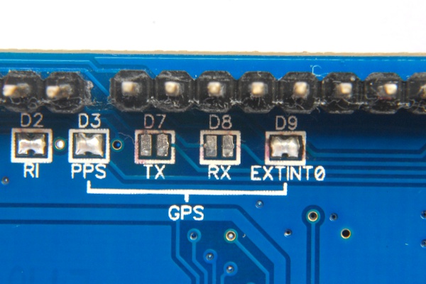
On a v2 TraLog shield, if all GPS module interface are being used, all solder jumper must be shorted as shown in the image below.
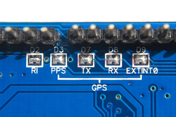
If you are using an Arduino Mega2560, the solder bridge on D7 & D8 must be removed and the hardware serial (Serial 2 or Serial 3 on Arduino Mega2560) shall be used via the Mega extension board (see Mega Extension Board section below).
GSM-GPRS Module
Both v1 & v2 of the TraLog shield comes with a Sierra Wireless’s WISMO228 GSM-GPRS module. This GSM-GPRS module is pre-configured to communicate through serial communication at 9600 bps. On v2 of the shield, a simple jumper settings is used to configure how they connected to the Arduino board. On v1 of the shield, a slide switch is provided to select the necessary pins.
| Pin | v1 | v2 |
| GSM-GPRS RX | D0, D1, D2, or D5 | D0, D1, or D5 |
| GSM-GPRS TX | D0, D1, D3, or D6 | D0, D1, or D6 |
Using software serial on a v2 shield with an Arduino Uno, Duemilanove or Leonardo, the following jumper configuration is required:
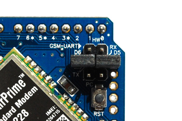
Using hardware serial on a v2 shield with an Arduino Uno, Duemilanove or Leonardo, the following jumper configuration is required:

If you plan to explore AT command using a terminal program to interact directly with the GSM-GPRS module, you can use the following jumper configuration. You’ll need to upload the “BareMinimum” Arduino sketch prior to that to allow direct communication between the GSM-GPRS module and your computer.
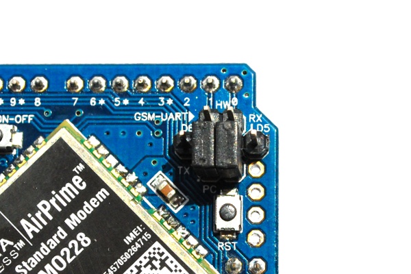
But if you plan to use an Arduino Mega2560, remove all jumpers and attach the Mega Extension Board (see the following section below) to the TraLog shield.
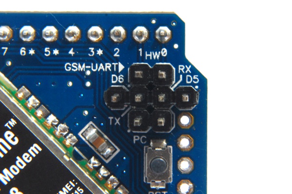
Mega Extension Board
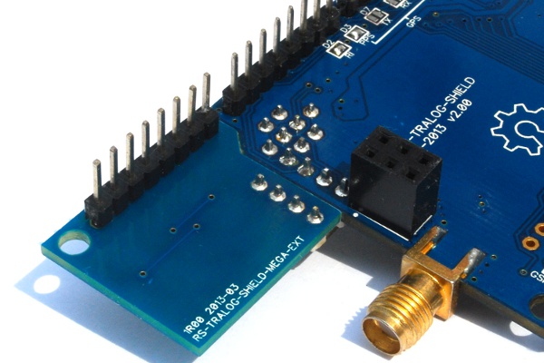
The usage of SoftwareSerial library on an Arduino Mega2560 is limited to certain pins only. The availability of 3 additional hardware serial on an Arduino Mega2560 board provides a more reliable serial solution compared to the software serial. In order to connect the serial lines of the GPS and GSM-GPRS module to the hardware serial of the Mega2560 board, we will need to use the Mega Extension Board. This board is only supported on v2 of the TraLog shield.
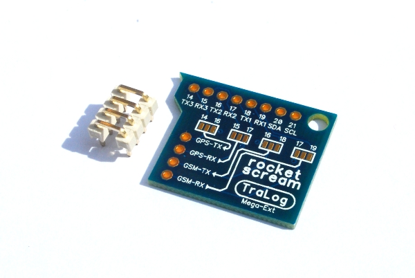
Using the Mega Extension Board, we can configure the:
- GSM-GPRS module to use hardware UART port 1 or 2
- GPS module to use hardware UART port 2 or 3
Using the 4-pin bridging connector, the TraLog shield is connected to the hardware serial through the extension board.
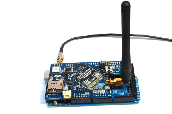
Here’s how it looks like mounted on an Arduino Mega2560! In the image below, the GPS module is connected to hardware serial port 3 and the GSM-GPRS module is connected to the hardware serial port 1.
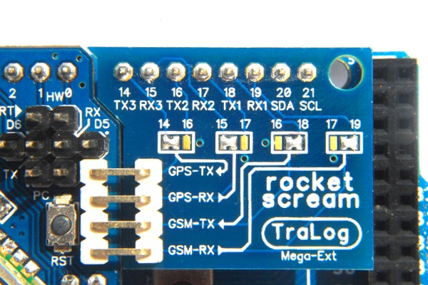
Arduino pin A2 is used to turn on and off the GSM-GPRS module and the solder jumper must be shorted (enabled by default) . Arduino pin A1 connected to the WISMO228-READY pin (connected by default) which can be used to check the readiness of the GSM-GPRS module is currently not supported on the WISMO228 library.

In order to detect incoming phone calls and new received SMS, the TraLog shield v1 & v2 uses Arduino pin D2 (connected to GSM-GPRS pin RI (ring indicator)) to provide an external interrupt when such event takes place. You don’t have to worry about polling for new SMS or having a big buffer when multiple new SMS is in storage when this feature is enabled. On v1 shield, short the RI and D2 lines on jumper J15. On v2 shield, short the RI and D2 lines together like the image below.

Antennas
And lastly we need to attach the GSM and the GPS antennas to the TraLog shield.
Up & Running
μSD
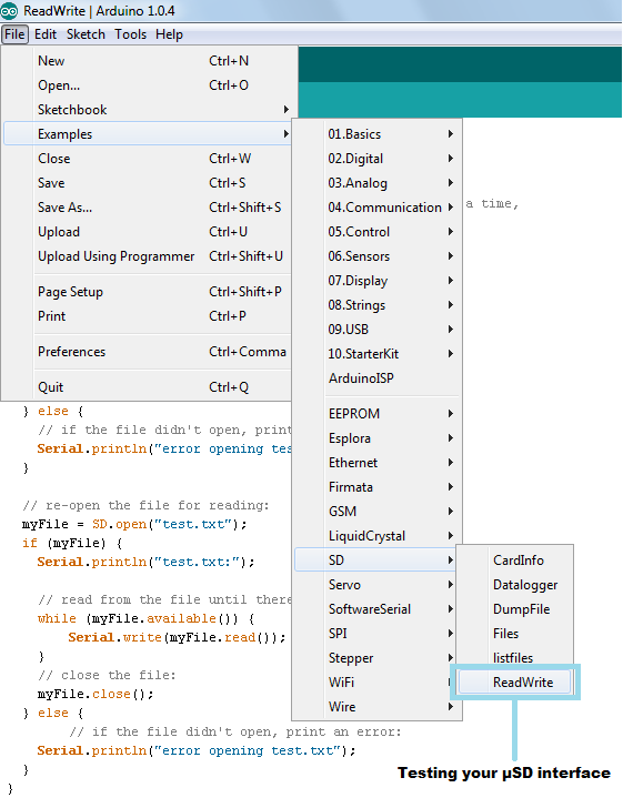
You’ll need the SD library which is bundled together in the Arduino IDE. The simplest exercise to understand how to use this library on the TraLog Shield, we recommend to start with the “ReadWrite” example bundled in the SD library. No pin configuration changes is required as the examples uses the same Arduino board pin assignment as the TraLog shield.
GPS
The GPS module on v1 and v2 of TraLog shield runs at different default baud rate:
| Shield Version | Baud Rate |
| v1 | 4800 bps |
| v2 | 9600 bps |
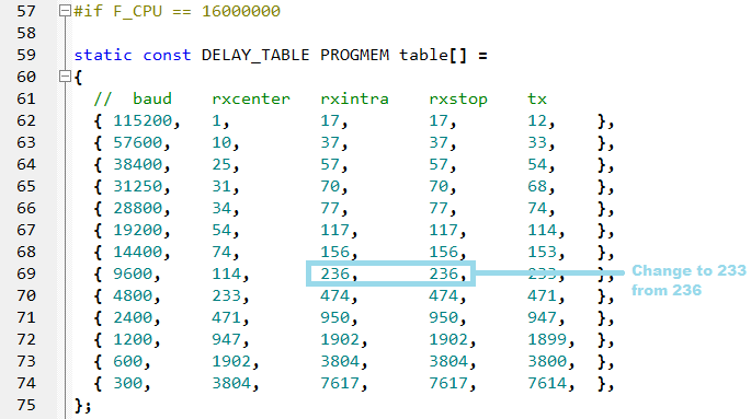
On v2 of the TraLog shield, the bit timing of the incoming GPS data does not work out of the box with the default configuration of the SoftwareSerial library. If you are using v2 shield on either an Arduino Uno, Duemilanove, or Leonardo, you’ll need to make some small changes to the SoftwareSerial library in the SoftwareSerial.cpp file as shown below for 9600 bps baud rate. This changes however does not affect the WISMO228 library (uses SoftwareSerial library too) operation and reliability. This tweak does not affect v1 of the TraLog shield.
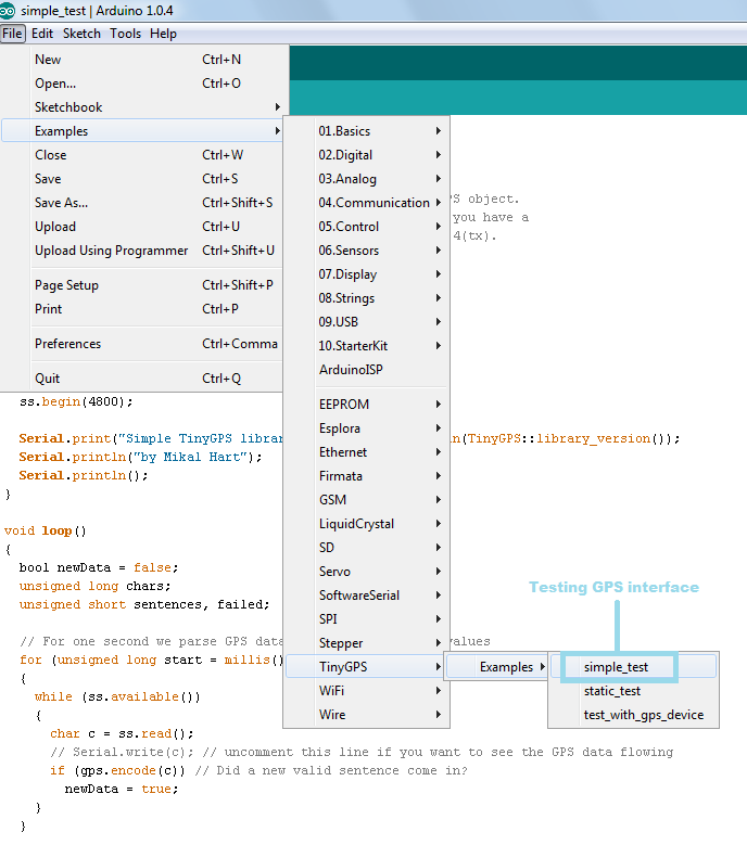
In order to decode the NMEA GPS data, the TinyGPS library is required. We recommend to start with the “simple_test” example bundled in the TinyGPS library.
If you are using an Arduino Mega2560, you need to feed the TinyGPS with the GPS NMEA stream from the hardware serial instead of the software serial shown in the above example. For example, if you are using hardware serial 3 for the GPS, the following sketch changes is required:
[code lang=”cpp”]
while (Serial3.available())
{
char c = Serial3.read();
// Serial.write(c); // Uncomment this line if you want to see the GPS data flowing
if (gps.encode(c)) // Did a new valid sentence come in?
newData = true;
}
[/code]
GSM-GPRS
Our Arduino compatible WISMO228 library simplify the use of the GSM-GPRS feature on the TraLog shield. Starting from version v1.20 of the library, hardware serial is supported on top of the software serial. The following code snippets uses the software serial on pin D5 and D6 of the Arduino board to communicate with the GSM-GPRS module. Please take note that, you will need to use the hardware serial if you are using an Arduino Mega2560 board.
[code lang=”cpp”]
const gsmOnOffPin = A2;
const gsmRxPin = 5;
const gsmTxPin = 6;
// Comment the next line of code if using hardware serial
SoftwareSerial gsm(gsmRxPin, gsmTxPin);
// Comment the next line of code if using hardware serial
WISMO228 wismo228(&gsm, gsmOnOffPin);
// Uncomment the next line of code if using hardware serial 1 (or 2)
// WISMO228 wismo228(&Serial1, gsmOnOffPin);
[/code]
Using either the software or hardware serial to communicate with the GSM-GPRS is not visible to the user except for the above object declaration section. All the examples bundled with the WISMO228 library can be used for both software and hardware serial providing that the above object declaration is followed.
Let’s TraLog Something!
Once you have tested all the components separately on the TraLog shield, you must be eager to put everything together!
Downloads
TraLog shield is an open source hardware product.
- Hardware design files are available on our GitHub repository.
- Libraries:
- Datasheets:
- Sierra Wireless WISMO228:
- uBlox MAX-6Q:


