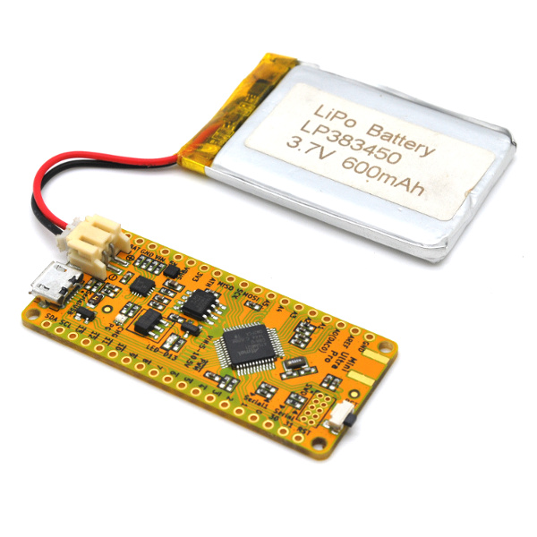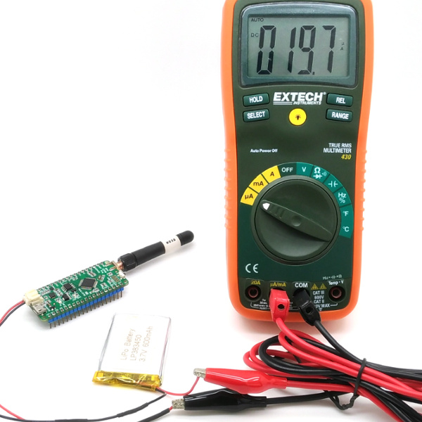
One of the most powerful feature of RTC is the ability to run in the lowest power mode possible on the ATSAMD21G18A-AU microcontroller. This allow the Mini Ultra Pro board to reside in ultra low power mode (21 µA or less of current only!) majority of the time and wake up upon alarm triggered by the RTC to perform scheduled tasks (sensor reading, data logging, radio communication, driving an actuator, etc).
Putting the Mini Ultra Pro into sleep mode (known as standby mode on the ATSAMD21 microcontroller series) will essentially stopping the main clock from running (which is also used to derived other clocks to drive peripherals). The important aspect of putting the Mini Ultra Pro into low power mode (a.k.a. sleep) is more than putting the microcontroller into standby mode. Identifying circuit components that could be driving excessive amount of current even when not in use is one of the crucial point to achieve the 21 μA or less of sleep current.
The following are the list of components on the Mini Ultra Pro that we need to take care of in order to achieve the low power current consumption in μA range.
- Radio module – either RFM95W or RFM69HCW:
- Both radio module can be put into sleep mode and only draws 0.1 μA of current
- Serial flash – S25FL116K0XMFI041 16 Mbit (2 MByte):
- The serial flash can be put into sleep mode and only draws 2 μA of current
- USB core of ATSAMD21G18A:
- USB bus must be in idle mode and in suspend condition in order to achieve low current mode
- Pins not in use on the Mini Ultra Pro:
- Pins that are not connected to any circuitry should be put into a defined state and not left floating
In this example, the RTC is configured to run in the background and an alarm is setup to wake up the microcontroller every 1 minute. Of course, this wake up interval can be configured as required by the application. The LED connected to pin D13 is toggle to indicate the sleep and wake up event. A Li-Ion/Pol 3.7 V is used to power the setup.
Take note that a 15 s delay in the beginning of the example is defined to provide ample amount of time for user to upload code before the USB device module detaches itself from the host. Once the Mini Ultra Pro board goes into low power mode, the PC will not be able to detect the USB serial port of the board unless the reset tact switch is press.
The measured current during sleep mode using the example code will result in 21 μA of sleep current. The bulk of the 21 μA is contributed by the on-board battery power management IC (BQ24074) but it is crucial to have a proper Li-Ion/Pol battery power management like the BQ24074 is avoid shorter lifespan of the battery due to unnecessary charge and discharge cycle.
/*******************************************************************************
 Mini Ultra Pro Sleep RTC Alarm
 Version: 0.10
 Date: 20-02-2017
 Company: Rocket Scream Electronics
 Author: Lim Phang Moh
 Website: www.rocketscream.com

 An example code demonstrating the ultra low sleep current capability of the
 Mini Ultra Pro while running the on-chip built-in RTC. Example puts the Mini
 Ultra Pro into standby mode (sleep) while RTC is allowed to run in the
 background. Alarm is set to wake the processor on the 15 s of a minute.
 This results in sleep period of 1 minute. The LED on pin 13 is set to toggle
 on every alarm match state. In sleep state with the built-in LED turn off,
 current measured is approximately 21.0 uA.

 Requirement:
 1. Mini Ultra Pro board powered by a single cell Li-Ion/Pol 3.7V battery.

 Important Note:
 1. Upon using the SerialFlash.sleep() function, the only function that the
 serial flash chip response to is SerialFlash.wakeup().

 Revision Description
 ======== ===========
 0.10 Initial public release.
*******************************************************************************/

#include <SerialFlash.h>
#include <RTCZero.h>
#include <SPI.h>
#include <RH_RF95.h>
//#include <RH_RF69.h>

// ***** CONSTANTS *****
const int radioDio0 = 2;
const int flashChipSelect = 4;
const int radioChipSelect = 5;

// Choose correct on-board radio
RH_RF95 radio(radioChipSelect, radioDio0);
//RH_RF69 radio(radioChipSelect, radioDio0);
RTCZero rtc;

/* Change these values to set the current initial time */
const uint8_t seconds = 0;
const uint8_t minutes = 00;
const uint8_t hours = 10;

/* Change these values to set the current initial date */
const uint8_t day = 20;
const uint8_t month = 2;
const uint8_t year = 17;

// ***** VARIABLES *****
unsigned char pinNumber;

void setup()
{
 // Switch unused pins as input and enabled built-in pullup
 for (pinNumber = 0; pinNumber < 23; pinNumber++)
 {
 pinMode(pinNumber, INPUT_PULLUP);
 }

 for (pinNumber = 32; pinNumber < 42; pinNumber++)
 {
 pinMode(pinNumber, INPUT_PULLUP);
 }

 pinMode(25, INPUT_PULLUP);
 pinMode(26, INPUT_PULLUP);

 if (!radio.init()){}
 radio.sleep();

 SerialFlash.begin(flashChipSelect);
 SerialFlash.sleep();

 pinMode(LED_BUILTIN, OUTPUT);

 digitalWrite(LED_BUILTIN, HIGH);

 // ***** IMPORTANT DELAY FOR CODE UPLOAD BEFORE USB PORT DETACH DURING SLEEP *****
 delay(15000);

 //***** UNCOMMENT FOR MINI ULTRA PRO VERSION 0V30 & ABOVE IF PINS ARE CONNECTED TO RADIO ****
 /*pinMode(6, INPUT);
 pinMode(7, INPUT);
 digitalWrite(3, HIGH);
 pinMode(3, OUTPUT);
 digitalWrite(3, HIGH);*/
 //*****

 // RTC initialization
 rtc.begin();
 rtc.setTime(hours, minutes, seconds);
 rtc.setDate(day, month, year);

 // RTC alarm setting on every 15 s resulting in 1 minute sleep period
 rtc.setAlarmSeconds(15);
 rtc.enableAlarm(rtc.MATCH_SS);
 rtc.attachInterrupt(alarmMatch);

 digitalWrite(LED_BUILTIN, LOW);
 USBDevice.detach();
 rtc.standbyMode();
}

void loop()
{
 // Initialize USB and attach to host (not required if not in use)
 USBDevice.init();
 USBDevice.attach();

 digitalWrite(LED_BUILTIN, !digitalRead(LED_BUILTIN));

 // Detach USB from host (not required if not in use)
 USBDevice.detach();

 // Sleep until next alarm match
 rtc.standbyMode();
}

void alarmMatch()
{

}


